


Next: 5. Wing
Up: QuickFlick-II Build manual
Previous: 3. Tail
Subsections
- 2 x 3.2mm notched sides
- 2 x 1.5mm forward doublers
- 2 x 3.2mm forward wing mount doublers (F6)
- 2 x 3.2mm rear wing mount doublers (F7)
- fuselage doublers F1, F2, F3, F4, F5
- 4 x 3.2mm wing mount crossbeams (for wing nuts)
- 1 x 3.2mm fuselage floor
- 2 x 58 x 18 x 6mm balsa blocks for holding boom
- 6 x 6mm triangular stock
Keeping the fuselage square and aligned at all times is a good start
for the rest of the QFII. However do not fret too much if the fuselage
is not absolutely perfect. Being a glider, subsequently without a
power plant on the nose, allows us to be more lenient in this area.
With all that said, please do still make your best attempt at keeping
the fuselage straight.
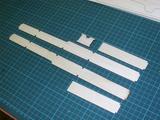
- Start out with the two notched 3.2mm fuselage sides, frontal 1.5mm
doublers and F2.
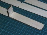
- Place F2 into the notches on one side of the fuselage, do not glue
in, we are using this as a guide stop for the placement of the doubler.
- Before applying the glue to the doubler, take note that there is a
slight orientation on the doubler, that is one of the corners is at
90 degrees and the other (top) is at 88 degrees. Although this is
a slight difference it will make the orientation of the doubler incorrect
if applied the wrong way up.
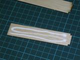
- Apply white glue to the frontal doubler, ensuring good coverage and
apply to the notched fuselage side. Make sure that the edges of the
doubler are adhered to the notched fuselage side, this is important
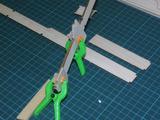
otherwise the doubler can peel off later. Clamping between two plates
or simply resting some heavy books on the doubler until dry should
help (place some balsa shims under the other side of the book if required
to ensure a level, even pressure).
- Formers F2,3,4 and F5 are all the same width and should rest at 90
degrees (perpendicular) to the fuselage sides.
- Remove F2 from the notches.
- Repeat for the other fuselage side creating a mirror image
of the first (yes, a couple of times we have done it wrong and ended
up with two left handed sides, very clever!)
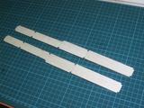
- Glue formers F2,3,4 and F5 to one fuselage side, ensuring that each
former is at exactly 90 degrees to the fuselage side. Please note
the orientation of the formers, ie,
- F2 should have its semicircular notch facing upwards
- F3 should have the two push-rod slots towards the top
- F4 and F5 should have the boom holes located at the bottom.
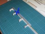
- Bring the second fuselage side of the fuselage against the existing
side with the formers now attached. Ensure that
- the work surface is flat
- the fuselage sides are held vertical during the gluing process
- the angle between the formers and the fuselage sides remains at 90
degrees when gluing
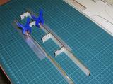
- Obtain F1 and dry fit it to the nose of the fuselage. If all is well
the fuselage should evenly bend towards F1. If the bending is uneven
and the fuselage takes on a banana appearance then place the fuselage
frame into a jig/rigging to keep it rigid and aligned while you join
F1.
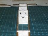
- You have now finished the basic framing up of the fuselage.
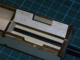
- Take the two F6 pieces, note that they are marked with 'FRONT' on
them, this means that the portion marked 'FRONT' will be orientated
towards the nose of the fuselage.
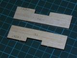
- Apply white glue to F6, insert and clamp.
- Make sure that F6 is sitting flush with the workbench and the top
of the fuselage side
- Make sure you clean up all the excess.
- It's very important that the bond of F6 to the fuselage side is strong
as there's going to be a lot of stress at this region.
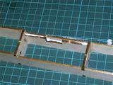
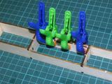
- Repeat procedure for the other fuselage side.
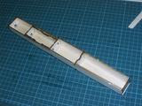
- Glue on the 3.2mm lower deck of the fuselage. If the lower deck is
slightly longer than your fuselage adjust the position so that the
excess length extends beyond F1.
The boom mount blocks are made from 6mm soft/medium balsa and require
a circular groove to be sanded into them of the diameter of the boom
that is to be used. One of the easiest ways is to sand them down using
sandpaper wrapped around a piece of the boom. Some people don't bother
with doing this and rely on the gap filling and strength of the glue
rather.
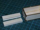
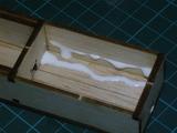
- Glue in each cheek between F4 and F5.
- Make sure that the cheeks are sitting flush to the bottom and side
of the fuselage
- Wipe away any excess glue
- You may want to test fit the boom while the glue is drying to ensure
the blocks will hold the boom correctly
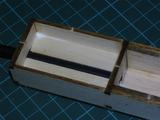
- As with F6, glue in the pair of F7 formers on top of the boom cheeks.
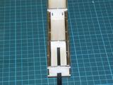
Although the fuselage is relatively strong in its standard form, it's
best to further add 6mm triangular stock in most corners to further
increase the rigidity of the fuselage.
- All four vertical corners between F2 and F3
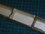
- All four vertical corners between F4 and F5
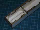
- Two corners on F2 facing F1
- Reinforcements between F3 and F4 on the floor between the fuselage
sides and the base plate.
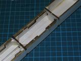
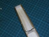
- Reinforcements between F1 and F2 on the floor between the fuselage
sides and the base plate.
Joining the carbon fiber boom to the fuselage is a very important
step which must be done accurately to ensure that when the QFII is
finished the alignment between the wing and the tail feathers is correct.
- Prepare your workspace such that there are no nearby items to obstruct
your assembly process.
- Check that the build surface you're going to use is flat, this is
very important.
- Obtain some 3.2mm scrap sheet, you will need this to keep the boom
level relative to the fuselage when we set it.
- If you're using 5 minute epoxy it is better to mix up an excess so
as to ensure you don't have insufficient glue half way through the
joining process as you will not have the time to mix up a second lot
- Have a ruler with mm or finer markings so that you can check
for the tail level once the glue has been added
- It is strongly recommended that you do not use CA for this
join as it generally lacks the flexibility required to cope with the
nature of the stresses encountered. Epoxy or polyurethane glues like
``Gorilla glue'' are preferred.
- Dry fit the boom into the fuselage. The boom should extend the fully
between F5 and F4. The boom should not extend beyond F4
- Place the assembly onto your workbench with the vertical stabilizer
just resting over the edge of the bench
- The horizontal stabilizer should still be located over the surface
of the bench, this is important as we will judge the alignment of
the boom based on the distance of the horizontal stabilizer from the
surface of the bench
- Weigh down the fuselage with something heavy to ensure it doesn't
lift or move during the gluing process
- Separate the boom from the fuselage after checking that everything
appears to be fitting correctly
- Sand the end of the boom lightly with 150~200 grit
paper to remove any sealing agents on the boom as well as providing
more glue surface area
- Mix up your glue as required
- Apply glue, ensure that there is good coverage of glue between the
boom and the balsa cheeks between F4 and F5. This join is one of the
most critical in the whole fuselage assembly.
- Reinsert boom into fuselage
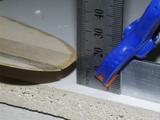
- Place 3.2mm scrap balsa at the edge of the bench under the boom (this
is because the base plate of the fuselage is also 3.2mm, so we are
keeping the boom level)
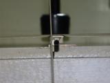
- Adjust the boom so that the distance from the work bench to the horizontal
stabilizer is the same on both sides
- Leave the boom and fuselage to set for as long as required.

This completes the basic build process of the fuselage. There is clearly
more work to be done before completion however there are other prerequisites
to be fulfilled before returning to finish the fuselage.
When the wing is completed, we will come back and add the wing mount
crossbeams, nose block and the optional tail block.


Next: 5. Wing
Up: QuickFlick-II Build manual
Previous: 3. Tail
Paul Daniels
2005-09-15


