


Next: 8. Servo installation
Up: QuickFlick-II Build manual
Previous: 6. Nose block and
Subsections
To ensure good control characteristics, the control rods must move
smoothly and with as little friction as possible as lower friction
means less wear on your servos, faster surface responses and a lower
drain on your battery.
Every builder has their preference for what method to use in the setup,
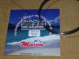
we will describe a 2-piece wire setup (per control) using 0.6mm (0.024'')
Chrome Nickel wire. The wire used in this section
is obtained from a fishing store, sold as stainless steel wire leader.
There are many different types of stainless steel wire, this particular
one is pre-straightened and has a spring steel / piano-wire feel.
As an alternative, you could also use 0.8mm (0.030'') or No.13 piano
wire.
Wire at the thicknesses used here does not have a lot of compressional
stability, it will tend to buckle out under compressional forces,
this is a highly undesirable trait. We counter this trait by supporting
the wire along the length of it with support tubes (tube sheath).
As with the wire, there are many options for support tubes. Some suppliers
provide sheath with their lengths of wire, other times you are required
to make it yourself. One option which does appear to work well is
to use cigarette wrapper papers (or other equally thin paper) that
have been gummed and rolled around a piece of wire that's slightly
larger than the wire that you intend to use for the control wires
(it must be slightly larger to prevent binding). See sec:Making-support-tubes
- Obtain a surface control horn (1mm ply) and line it up on the rudder
with the series of drill holes directly over the hinge line of the
vertical stabilizer. Move the horn up such that the base of the horn
is aligned just slightly below the bottom of the CF boom.
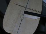
- Mark the the location of the base of the control horn with a pen,
this is where we will cut out a slot that the control horn will be
placed. The control horn must be just slightly lower than the boom
so as to allow for the control wire to slide freely without binding
when the control horn is pulled inwards towards the boom.
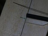
- Trim off the bottom elbow of the control horn, this is required so
that the horn doesn't obstruct into the vertical stabilizer when it
is pulled forward
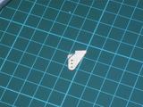
- Using a sharp No.11 blade or similar, cut out a 1mm wide slot in the
location marked
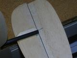
- Insert control horn into slot, test for movement and potential binding
against the vertical stabilizer. If all appears good then glue the
control horn in with a small amount of epoxy or medium to thick CA.
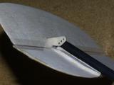
The elevator control horn installation is mostly the same as the rudder
installation however instead of being aligned as close to the boom
as possible, the elevator is typically offset by 6mm from the boom.
Take care when cutting the slot for the horn as the elevator is typically
weaker near the cutaway (for the boom).
- Mark the location and size of the slot to be cut in the elevator.
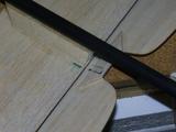
- Cut out slot and insert control horn
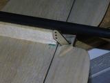
- Check and glue the control horn
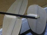
- Cut two lengths of wire from F2 to the end of the boom, this will
provide more than ample length for the installation
- Insert and glue a length of tube between F4 and F5, leave a little
protruding from each end, especially the rear of F5 (this is so that
if you put the optional rear fairing block on, you do not run the
risk of gluing the tube shut).
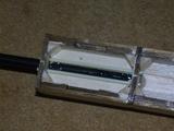
- Insert wire into the tube guides between F4 and F5 and push the wire
in until it reaches F3
- Slide onto the wire 5 pieces of 60mm long rolled tube
- Push the first piece to butt up against the protruding tubes emerging
from F5
- Tack down the tube with a small amount of CA
- *WARNING*, be very light with your application of CA, because
the tubes are made from paper they can be exceptionally quick to wick
the CA into the center of the tube and subsequently glue the tube
to the wire leaving you with the choice of having to pull everything
out again or try to break the wire free.
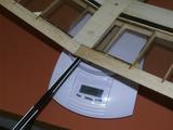
- Space the rest of the tubes evenly along the boom, following the curve
required for the wire to reach its appropriate control horn.
- Tape the wire down near the control horn to make the wire show you
what path it prefers to take
- Do not force the wire to make aggressive bends, this only causes more
friction on the run
- For the rudder, the wire must eventually run along the underside of
the boom
- For the elevator, the wire will need to veer off from the boom at
the end and be supported with a small wedge of balsa
- Each time you tack down another tube check the movement of the wire
and ensure there's no binding or excessive friction
- For the elevator make a 3~5mm L bend at the end of
the wire and insert into the control horn's outer hole
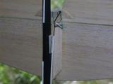
- For the rudder make a 3~5mm L bend at the end of the
wire and insert into the control horn's middle hole
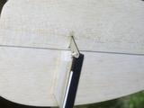
- Cut the wires at 15mm after F3 (ie, the wire ends between F3 and F4)
- Check your assembly for binding
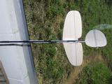
- Add a small scrap of 2.4mm balsa into the fuselage just forward of
F4 such that the wires just rest on it
- Glue two small lengths of tube onto the balsa scrap platform to support
the wires. This is done to reduce the unsupported distance between
the exit of F4 and the servo arms.
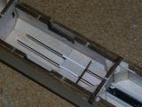


Next: 8. Servo installation
Up: QuickFlick-II Build manual
Previous: 6. Nose block and
Paul Daniels
2005-09-15


